- Submit data
- What do we do with your data
- Database design
Database design

The design of BODC's databases have developed over the years to support the evolving nature of data collected by oceanographers.
Oracle Relational Database Management System (RDBMS)
Our databases adhere to the relational model of database design and use the Oracle Relational Database Management System (RDBMS).
The databases store information in tables. Tables consist of columns (fields) and rows (records). Each row should be unique and can be identified using a primary key. A primary key consists of one or more fields whose value (or values) are unique.
Tables can have relationships or links with other tables. A value (e.g. a parameter code) stored in one table can have more information stored about it in another table. This approach helps to minimise duplication of information.
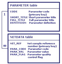
Figure 1 illustrates the relationship between a plankton net data table (NETDATA) and a parameter table (PARAMETER). The field PARA_CODE in NETDATA links to CODE in PARAMETER. PARAMETER contains more information about the parameter that was measured
The relationship between PARAMETER and NETDATA is one-to-many. Each row in PARAMETER corresponds to one type of parameter. The rows in NETDATA can store the same parameter code many times.
National Oceanographic Database (NODB)
The NODB stores metadata (data about data) in a relational database in the form of a data series. Metadata includes the data originator, position and collection start/end dates and times. The actual data measurements are stored outside the database in binary data files. These data are available by online delivery via our NODB data series facility.
The concept of a data series is fundamental to the design of the NODB. Each series consists of a number of data cycles. Each data cycle usually contains one value for each parameter sampled. Examples include
- a year of tide gauge data measuring sea level at a given location every 15 minutes.
- a CTD profile measuring temperature and salinity every 2 m from the sea surface to the sea floor at a particular place and time.
Each data series has one row in the master NODB table. The table links to other NODB tables containing metadata about parameters, restrictions, documentation and storage.
The NODB was originally developed by Meirion Jones and Trevor Sankey using a COnference on DAta SYstems Languages (CODASYL) system. Its aim was to improve the availability of oceanographic data for science and industry, as well as to protect it for future use - functions the NODB still performs today.
Project (samples) Database
The Project Database (later known as the Samples Database or Samples Schema) was used to manage data for large multi-disciplinary research projects. Both the metadata and the data measurements themselves are stored in the Oracle RDBMS. It was created in 1988 when BODC took on data management for the North Sea Project.
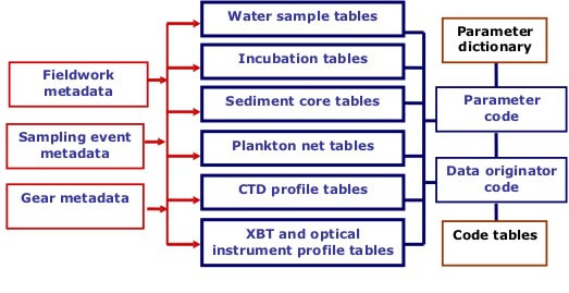
Advances in the technology used by oceanographers had dramatically increased the number of measureable parameters. At the time, the NODB could not support such large numbers. BODC developed a new database schema, organised around three main groups of tables
i. Sampling metadata tables consist of sampling and event description tables. These link to the fieldwork description table and to the sampling instrument or gear code table.
ii. Data tables consist of a series of data storage tables for each main type of sampling or data collection technique.
iii. Parameter dictionary tables define the eight-byte parameter codes used to label the measurements in the data tables.
The data table structure has been adapted and modified for each main type of data collection technique. This enables storage of specific metadata information, such as bottle depth and type for water collection events and plankton net depth range, mesh size and mouth area for plankton net hauls. All data tables have the same field structure consisting of a
- primary key
- parameter code
- data value
- quality control flag
- originator code
- loading date
This structure enables easy expansion to include new sampling instruments, methodologies and parameters. Figure 2 illustrates the flow of data into the Project Database.

The Project Database was later incorporated into the NODB. Both infrastructures are used in parallel.
Web Database
Increasingly, data is delivered via the web. We continually develop our Web Database to meet the specific needs of web applications. Issues such as security and performance are critical when exposing data to the internet.


